Going retro - analogue gauges
Share
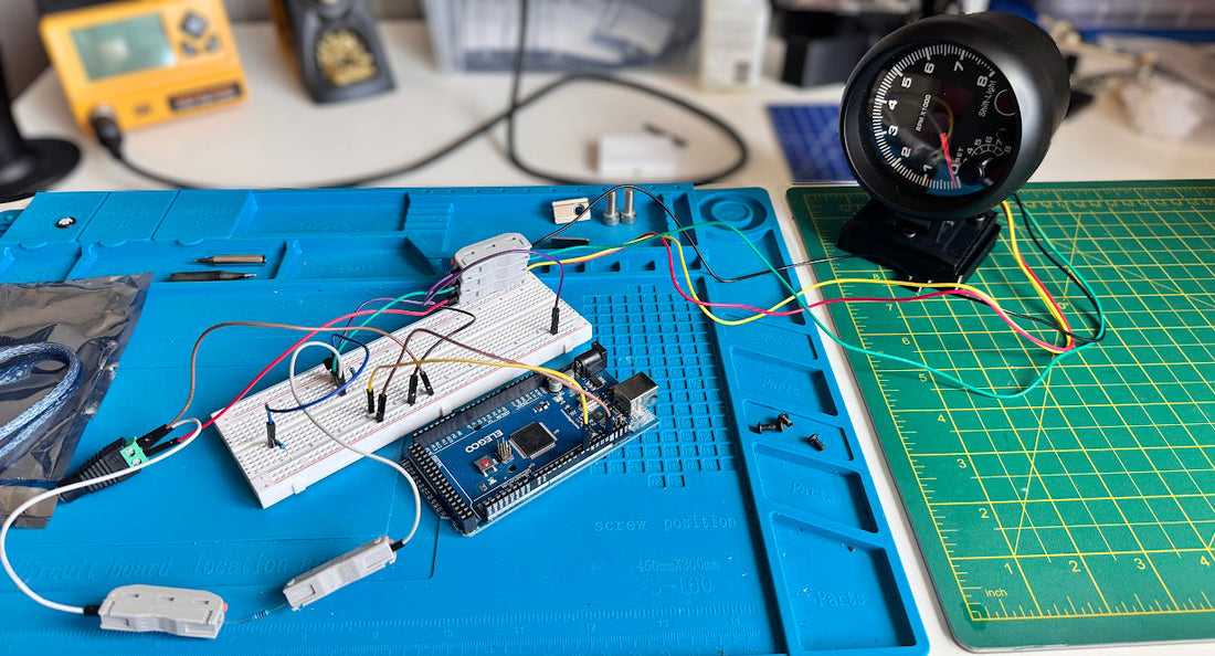
At Anorak Sim Gear, we’re always exploring new ways to bring realism to the sim racing experience. Recently, I set out to prototype a physical analogue tachometer — the kind you'd find in a real car — and have it respond to RPM data in real time from SimHub.
At first glance, it seemed simple: hook up a gauge, control it with an Arduino, job done. In reality? Not quite.
The Challenge of Driving a Real Gauge
Unlike LEDs or hobby servos, an automotive-style tachometer expects a very specific type of signal — essentially a pulsed voltage, mimicking an ignition coil or ECU signal from a real vehicle. That’s not something a microcontroller like an Arduino outputs directly. So we had to get clever.
Signal Translation: Enter the Transistor
To convert logic-level outputs (like those from an Arduino) into a high-voltage pulsed signal, I initially used a TIP120 Darlington transistor. It worked — but it was bulky, and it got warm. After some experimenting, I swapped it out for a much smaller 2N7000 N-channel MOSFET, which turned out to be a better fit for both performance and PCB real estate.
However, transistors have quirks. At high RPMs, the gauge started to behave erratically — dropping to zero or fluttering. After some head-scratching, the fix turned out to be a simple 10kΩ pull-down resistor on the transistor’s gate to ensure a clean signal.
Voltage Management and Power
The tachometer needs 12V, but my Arduino doesn’t supply that natively. I considered adding a DC-DC booster module to step up from 5V to 12V inside the enclosure — but that raised concerns about heat, interference, and switching noise.
Ultimately, I used a dedicated 12V line to power the gauge, with a switch to allow it to be powered down independently — though we’re also exploring having the gauge only power on when the Arduino is active, to streamline setup and avoid surprises.
Designing the Enclosure
Packaging everything in a neat enclosure took just as much thought. I designed a custom mount that hides the Arduino and leaves room for expansion — maybe a boost or speed gauge in the future. PLA+ worked well for strength and printability, though PETG would be better in hotter environments.
Lessons Learned
This project is a perfect example of how “simple” ideas become engineering puzzles. The mechanical gauge, while retro and satisfying, introduces challenges in signal conditioning, voltage compatibility, and physical integration.
But that’s what makes sim racing hardware fun — taking real-world components and giving them a second life in a virtual cockpit.
Next Steps
I’ve already had a batch of PCBs manufactured for a production version of this board, and they include all the fixes discovered during prototyping. Now it’s time to start thinking about enclosure designs and exploring whether this analogue approach could complement our other visual feedback tools, like the iFlag and digital rev gauge.